1.Feeding:
No. | Part / System | Specification | Remarks |
1 | Feeding Type | Lead Edge Feeder | Three shafts |
2 | Feed Roll | Upper : Full Rubber coated roll;Lower: Knurled steel roll | Reduce damage to the flute |
Manual feed roll caliper control |
|
Range of caliper : 0 mm ~ 12 mm |
|
3 | Back Guide | Computer setting and/or motorized forward and backward |
|
Manual up/down control |
|
4 | Side Guide | Computer setting and/or motorized setting |
|
Pneumatic powered side jogger on operator side | Improve precision |
5 | Front Gate | 2 pcs of movable front gates |
|
Manual front gate caliper control |
|
6 | Suction Blower | Heavy duty, low noise, suction blower |
|
Suction control damper according to board size |
|
Silencer installed |
|
Variable suction volume to match different board size | Transducer control |
7 | Sheet Cleaner | Suction blower for sheet cleaning | Transducer control volume |
Brush for sheet cleaning |
|
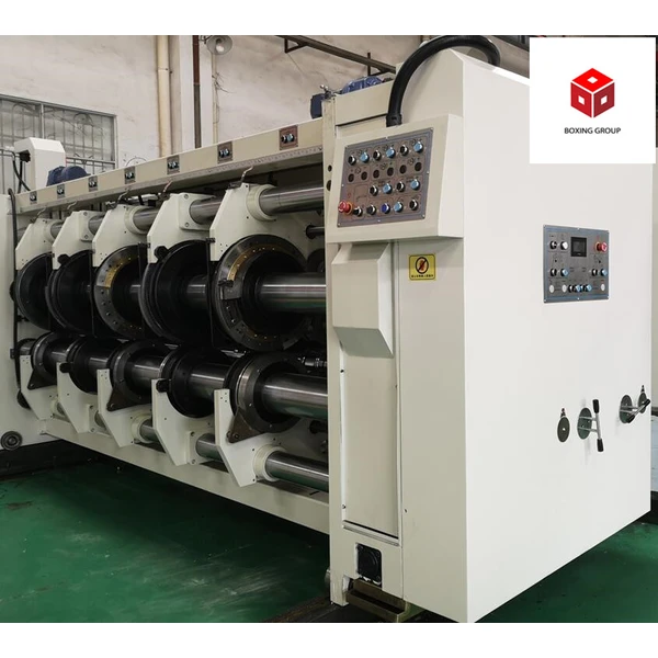
2.Printing:
No. | Part / System | Specification | Remarks |
1 | Print Cylinder | Thickness of printing die : 7.2 mm |
|
Plate mounting method: KSL fast mounting type. | Lock with ratchet wheel |
Computer setting and/or motorized lateral adjustment : 10 mm | Screen display |
Print cylinder rotates by treading foot switch |
|
2 | Anilox Roll | Steel Anilox roll,Ceramic anilox roll for optional. |
|
Mesh of anilox roll | Specified by customer |
Manual Anilox roll caliper control |
|
Automatic up/down of Anilox roll when feeding stop/start | By air cylinder |
Added function of idling when stop printing to avoid ink drying on the anilox roll |
|
3 | Inking system | Rubber roll inking, doctor blade inking for optional. |
|
Manual caliper control | Self-lock |
4 | Ink pump | Diaphragm ink pump with filter and low ink detector |
|
5 | Pull roll | Self-lock device, easy to move and fasten |
|
6 | Register System | Printing register is digital controlled by motor and PLC | Through planetary gear |
Easy to control by means of reset “0” system | Quick and correct control |
7 | Ink System | Diaphragm type ink pump |
|
Automatic ink washing with water supply |
|
8 | Indicating Lamp | Machine operation or Frame open/close | Same fashion in every machine unit |
Lack of Ink on print unit |
Emergency stop or over load trip |
9 | Automatic Zero (0) | Automatic zero return by sensor |
|
10 | Automatic restoration | A fixed device for the printing register and brake for the electromagnetic clutch is used when unit open | Keep the register |
The printing register is precisely saved in PLC |
|
The register is restored upon unit closing even the register changed during this period |
|
11 | Frame Open / Close | Driven by electric motor on feeder unit |
|
Pull switch or Emergency stop switch for safety during setting / maintenance |
|
12 | Frame Locking Device | Mechanical locking device by air cylinder control | Automatic locking |
13 | Lubrication system | Circular lubrication system by oil pump in every unit |
|
14 | Emergency Stop | Emergency stop switch equipped on operation panel |
|
3.Slotting:
No. | Part / System | Specification | Remarks |
1 | Structure | 8 shafts slotting unit, with 3 sets of creasing and 1 set slotting.Pre creasing, big creasing and fine creasing ensures good creasing effect and improves the folding effect. |
|
2 | Pre-creasing wheel | Automatic lateral adjustment | Screen display |
Manual roll caliper control | Self-lock |
3 | Creasing wheel | Automatic lateral adjustment | Screen display |
Manual shaft caliper control | Self-lock |
4 | Slotter | Automatic lateral adjustment | Screen display |
Manual roll caliper control | Self-lock |
Central blade is movable |
|
5 | Pull roll | Self-lock device, easy to move and fix |
|
6 | Register System | Slotting register is digital controlled by motor and PLC | Planet-gear |
Easy to control by means of reset “0” system | Quick and correct control |
7 | Automatic Zero (0) | Automatic zero return by sensor |
|
8 | Frame Open / Close | Driven by electric motor on feeder unit |
|
Rope pulled switch for safety during setting / maintenance |
|
9 | Lubrication system | Circular lubrication system by oil pump in every unit |
|
10 | Emergency Stop | Emergency stop switch equipped on operation panel |
|
4.Die Cutting:
No. | Part / System | Specification | Remarks |
1 | Die cut drum | Motorized lateral adjustment within 10 mm | Screen display |
2 | Anvil drum | Manual feed roll caliper control | Dial indicate |
Mechanical lateral oscillating of anvil drum within ±20 mm | Distribute wear of anvil cover |
Durable rubber covered, easy assembly and disassembly |
|
3 | Pull roll | Self-lock system, easy to move |
|
4 | Register System | Die cutting register is digital controlled by motor and PLC | Through planet-gear |
Easy to control by means of reset “0” system | Quick and correct |
5 | Automatic Zero (0) | Automatic zero return by sensor |
|
6 | Frame Locking Device | This unit is unmovable |
|
7 | Lubricating Oil Pump | Gear type oil pump on every machine unit |
|
8 | Emergency Stop | Emergency stop switch equipped on operation panel |
|
9 | Scrap conveyor | Install under the die cutting unit |
|
10 | Anvil Grinding System | Sand roller micro grinding system, prolong the anvil cover using life and increase the grinding efficiency. |
|

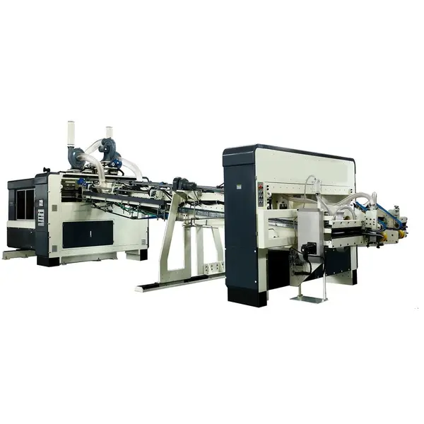
5.Inline Fold Gluing:
5.1 Configuration List
u Wheel gluing system with automatic recycle pump
u Folding section
u Driving section
u Stacking and ejector section
u Full computerized controlling
5.2 Wheel Gluing System
u Wheel gluing system with automatic recycle pump.
5.3 Folder Gluer
u Paperboard be run forward by former convey belts consisted of up and lower belt. The gap of entrance and up and lower belt can be adjusted automatically.
u Pressure wheels of entrance are loaded by springs while limit device can adjust the gap between every pressure wheel and lower folding beam independently.
u Solid folding beams with strong rigidity and good stability suit high speed running.
u There are two set side pressure wheels against the folding knife to ensure folding lines precise.
u Back and convey belt with vacuum holes prevent sliding to form shear fork.
u Lower folding belt which speed is higher than vacuum belt avoid shear fork.
u There are two set correcting wheels to ensure box square.
u Folding beams move left and right adopts motor-controlling and also adjust automatically according orders.
5.4 Counter Ejector
u Photoelectric sensor counting accurately.
u Three group of servo motors finish the function of precise counting, stacking and conveying out while high speed running.
u Servo control high speed separating bar to stack according required quantity per pile.
u Pneumatic assistant supporting bars make boxes stacking flat.
u Pile boxes ejected by pneumatic pushing plate in order.
u Strong wind pressure which direction can be adjusted anywhere protect boxes bend upwards.
u Backboard motorized move adjusting (automatically or manually) according box’s spec. The buffering pad of the backboard decreases the impact to the edge of the carton when high speed running.
u Both up and lower convey belts transfer pile boxes together.
u The position of up belt can be adjusted automatically or manually according the quantity per pile.
u Eject section can move to left and right to make boxes always fall down on the center of table.
u The ejecting quantity of cartons can be automatically set in computer. It can be 10 pieces up to 20 pieces.
5.5 Driving Section
u Frequency conversion motor runs in step with printer.
u All synchronize belts driving are structure simple, noise lower, running steady and vibrate lower.
u Moving parts are formed with imported ball screw rod and straight line rail.
Option models:
Data/Model | 900x2000 | 1200x2400 | 1200x2800 | 1400x2400 | 1400x2800 | 1600x2800 |
Printing Speed(m/min) | 200 | 200 | 200 | 200 | 200 | 200 |
Max Machine Speed(pcs/min) | 300 | 250 | 220 | 220 | 200 | 200 |
Max Feeding Size(mm) | 880x2000 | 1180x2400 | 1180x2800 | 1380x2400 | 1380x2800 | 1540x2800 |
Min Feeding Size(mm) | 290x640 | 340x700 | 340x700 | 360x700 | 360x700 | 440x760 |
Skip Feeding(mm) | 1100x2000 | 1500x2400 | 1500x2800 | 1700x2400 | 1700x2800 | 1900x2800 |
Max Printing Area(mm) | 800x2000 | 1150x2400 | 1150x2800 | 1320x2400 | 1320x2800 | 1540x2800 |
Thickness of Printing Plate(mm) | 7.2 | 7.2 | 7.2 | 7.2 | 7.2 | 7.2 |
Max Slotting Depth(mm) | 250 | 320 | 320 | 320 | 320 | 560 |
Max Thickness of Sheet(mm) | 8 | 12 | 12 | 12 | 12 | 12 |